Return to Hobie.com
Hobie Forums
It is currently Tue Apr 16, 2024 4:26 am

All times are UTC - 8 hours [ DST ]


Post new topic Reply to topic  [ 16 posts ]  Go to page 1, 2  Next
Author Message
PostPosted: Thu Oct 02, 2014 8:56 am 
Offline
Site Rank - Old Salt

Joined: Thu Sep 17, 2009 12:35 pm
Posts: 313
Location: Lake Champlain, Vermont
While waiting for a used crossbar to show up close by, I'm repairing this. :shock:

Image

Pulled up an inch or so and I sail in some tough conditions! Held together nicely. I am making an SS backing plate and riveting on with some epoxy (with filler) to make a tight connection. That'll give me a couple years. More to come.

Image

Image

_________________
H18, H17 & Various motor boats


Top
 Profile  
 
PostPosted: Thu Oct 02, 2014 3:40 pm 
Offline
Site Rank - Old Salt

Joined: Mon May 09, 2005 10:25 am
Posts: 4178
Location: Jersey Shore
Wow, that's really bad. Coincidentally, I took my boat apart last week for winter storage and noticed some cracking and corrosion on my front crossbar too. It's not nearly as bad as yours, but I will be working on reinforcing and repairing my crossbar as well. It looks like Hobie must have increased the size of the reinforcement plate inside the crossbar at one point. Yours only has two rivets, but the one on my boat has six rivets. One of the main problems with the design, I think, is that the rivet holes are too close to the slot for the dolphin striker. They tried to cram too many holes/fasteners into a small area.

My crossbar has a crack about 2 or 3 inches long starting at one end of the crossbar and running parallel to the axis of the crossbar. The crack is right next to the trampoline track and I suspect it was caused by the crossbar being forced against the end casting as the crossbar tries to rotate. I plan to get this crack welded. I will also add two rivets to each end of the crossbar to secure the crossbar to the end casting to help spread out the rotational load (torque) on the end of the crossbar.

I also have a small crack starting at the mast step and I will either get this welded or drill a small hole at the end of the crack to hopefully stop it from getting larger.

Last, there is cracking and corrosion around the rivet holes in the bottom of the crossbar near the dolphin striker reinforcement bar. I plan to make a larger reinforcement plate which will be sandwiched between the existing plate and the inside of the crossbar extrusion. The current plate stops right at the inboard side of the hull and I plan to make the new plate extend an inch or so farther to help spread out the load. I also plan to coat everything in tef-gel before reinstalling to prevent any more corrosion from forming. I'll try to post pics of the repair.

sm


Top
 Profile  
 
PostPosted: Fri Oct 03, 2014 5:03 am 
Offline
Site Rank - Old Salt

Joined: Thu Sep 17, 2009 12:35 pm
Posts: 313
Location: Lake Champlain, Vermont
Yeah, your plan sounds reasonable. My cracks are corrosion induced so drilling won't do anything. I like the Tef Gel idea.

I only took mine apart cause it was leaking like a sieve. Now I see why- water enters these holes, drains to the ends, leaks slowly via the end cap holes into the hulls.

Anyway, I pressed/hammered/vice'd a couple plates to fit the inside shape of the extrusion. I think its some heavy aluminum- not sure SS would be any better since the weak link is the crossbar. This was hard enough to bend. Put some primer on for fun and will look for the galvanic paint stuff today.
Image
Image
The plan is to dry fit assemble to get the rivets in place for the bracket, then lock it in place with 6 or so rivets each side. Like SM said, too many rivets in a short distance is probably worse than more.

Image

_________________
H18, H17 & Various motor boats


Top
 Profile  
 
PostPosted: Fri Oct 03, 2014 9:15 am 
Offline
Site Rank - Old Salt

Joined: Mon May 09, 2005 10:25 am
Posts: 4178
Location: Jersey Shore
Looks like you are definitely on the right track. I would almost think it might we worthwhile welding your new reinforcement plates in all around the cracked out area of the crossbar.

There was definitely a design change to the stainless brackets. The one from my crossbar is longer and is a different design than yours. What are the small square brackets in the bottom of the picture? Are they for the rear crossbar? You may also want to consider beefing up the rear crossbar plates as well. I know for a fact that Hobie also increased the size of those plates making them about 4" long. The rear crossbar on my old boat had the smaller plates and it eventually started cracking out.

Anyway, thanks for sharing.

sm


Top
 Profile  
 
PostPosted: Fri Oct 03, 2014 10:21 am 
Offline
Site Rank - Old Salt

Joined: Thu Sep 17, 2009 12:35 pm
Posts: 313
Location: Lake Champlain, Vermont
Those are washer/spacers for the nut. Can't use them with the new plate- too thick. Cut some fender washers for that.
Image

_________________
H18, H17 & Various motor boats


Top
 Profile  
 
PostPosted: Fri Oct 03, 2014 10:24 am 
Offline
Site Rank - Old Salt

Joined: Thu Sep 17, 2009 12:35 pm
Posts: 313
Location: Lake Champlain, Vermont
Dry fit everything then riveted the new plate to the bracket
Image
Then installed
Image

Image

Image

Rear x bar is bad too but that'll be easier since it's just a BIG "washer"

_________________
H18, H17 & Various motor boats


Top
 Profile  
 
PostPosted: Fri Oct 03, 2014 1:06 pm 
Offline
Site Rank - Old Salt

Joined: Thu Sep 17, 2009 12:35 pm
Posts: 313
Location: Lake Champlain, Vermont
srm wrote:
Looks like you are definitely on the right track. I would almost think it might we worthwhile welding your new reinforcement plates in all around the cracked out area of the crossbar.


sm


Re welding. Some smart General Dynamics submarine welder would have to convince me that welding this tempered extrusion would be strong after that much heat and I'm sure my aluminum plate is not the same makeup as the xbar al. I have a mig and wouldn't dare do it myself (and I couldn't pay someone to do it!)

Let me know what you know about it

_________________
H18, H17 & Various motor boats


Top
 Profile  
 
PostPosted: Fri Oct 03, 2014 4:56 pm 
Offline
Site Rank - Old Salt

Joined: Mon May 09, 2005 10:25 am
Posts: 4178
Location: Jersey Shore
I'm no expert when if comes to welding, but I think a lot of it comes down to the skill of the welder and how good they are at controlling the heat. My thought was that you just have a large hole in the bottom of the crossbar and welding that opening to the reinforcement plate would help to connect the plate to the crossbar and further spread out the load.

One issue I see is that you didn't use countersunk rivets. Are you planning to drill out recesses in the hull saddle where the rivet heads make contact so the crossbar surface will sit flush with the hull?

Otherwise, I think your repair looks really good and this should be a huge improvement over what you had.

sm


Top
 Profile  
 
PostPosted: Sat Oct 04, 2014 3:09 am 
Offline
Site Rank - Old Salt

Joined: Thu Sep 17, 2009 12:35 pm
Posts: 313
Location: Lake Champlain, Vermont
Thought about that but the tolerance in there was so sloppy and my bedding calk was still on the tube about that thickness. Think I used 4200.

_________________
H18, H17 & Various motor boats


Top
 Profile  
 
PostPosted: Sat Oct 04, 2014 6:03 am 
Offline
Hobie Approved Guru

Joined: Mon Jul 14, 2003 7:11 pm
Posts: 5197
Location: Detroit, MI
srm wrote:
I'm no expert when if comes to welding, but I think a lot of it comes down to the skill of the welder and how good they are at controlling the heat.

The tempering process (T6) uses an initial heat of 980° F for an hour, quench, then "aging" at 325° F - 400° F for 1 to 8 hours (lower heat, longer time).

In contrast, the melting point of 6061 aluminum alloy is 1202° F - the minimum temperature of the weldment. There's no doubt that welding will remove the temper from the extrusion. The only question is how large the heat-affected zone (HAZ) will be. Aluminum conducts heat well (second only to copper), so the HAZ tends to be much larger than a comparable steel weld unless special precautions (heat sinks) are used.

Additionally, aluminum needs to be almost surgically clean for solid welds. The slightest bit of contamination (like corrosion or steel dust) will result in an inferior weld with high porosity. I used to work at a shipyard when we tried to move aluminum production into a building that had been used many years for steel production. The resulting fiasco, caused by residual steel dust contaminating the welds, was of epic proportions. It was cheaper to just build a new building exclusively for aluminum production.

Using mechanical attachments for this repair is the best solution, although I'm concerned about the rivet heads tearing up the crossbar saddle, too.


Top
 Profile  
 
PostPosted: Sat Oct 04, 2014 6:58 am 
Offline
Site Rank - Old Salt

Joined: Thu Sep 17, 2009 12:35 pm
Posts: 313
Location: Lake Champlain, Vermont
MBounds wrote:
srm wrote:

Additionally, aluminum needs to be almost surgically clean for solid welds. The slightest bit of contamination (like corrosion or steel dust) will result in an inferior weld with high porosity.


I had no chance of finding clean weld on this piece. Just too many ways for that process to go wrong. (and I like testing :mrgreen: )

I'll keep you posted on the fitment in the saddle.

_________________
H18, H17 & Various motor boats


Top
 Profile  
 
PostPosted: Sun Oct 05, 2014 9:52 am 
Offline
Site Rank - Old Salt

Joined: Mon May 09, 2005 10:25 am
Posts: 4178
Location: Jersey Shore
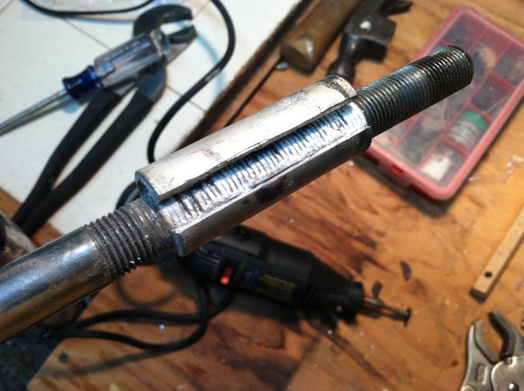
Since we're on the topic of front crossbar corrosion, I thought I'd add some info about the dolphin striker. If you've ever tried to adjust or remove the dolphin striker post on a H17 and couldn't understand why it wouldn't budge, the reason is almost certainly galvanic corrosion...a lot of it.

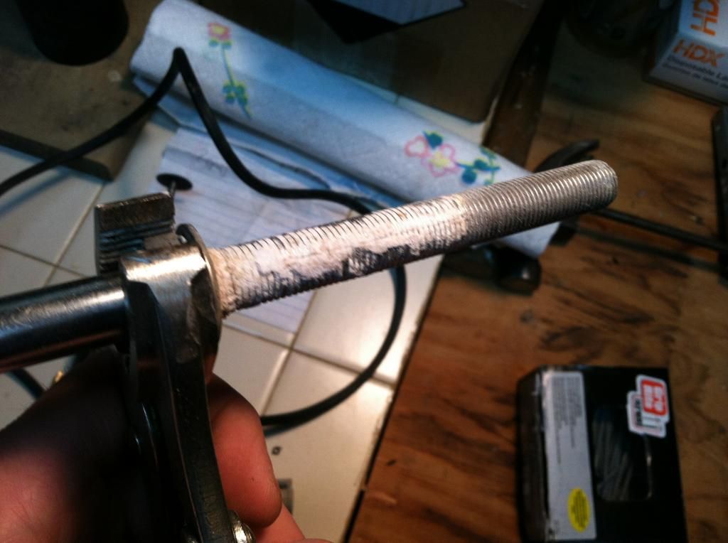
There is an aluminum sleeve that slips over the stainless steel dolphin striker post inside the front crossbar. The purpose of this sleeve is to transmit the force from the upper dolphin striker post nut down to the bottom of the crossbar extrusion. This holds the post firmly to the crossbar and also prevents over-tightening the nuts and crushing the crossbar. The hole in the bottom of the crossbar is slightly larger than the diameter of the dolphin striker post, and the hole in the top of the crossbar is slightly larger than the outside diameter of the sleeve. The problem is that, if you've ever sailed your boat in salt water or if your crossbar has been assembled for any significant period of time, galvanic corrosion between the sleeve and the post will seize the two together.

Since the bottom hole of the crossbar is too small for the sleeve to pass through and the bottom nut on the post prevents the post from being lifted upward out of the crossbar, the post will be stuck on the crossbar. The only way to remove the post is to cut off the bottom nut. Then the post and sleeve can pass through the upper hole in the crossbar. This is what I did and here's what I found when I cut the sleeve off of the post...

Image

Image

The post had a continuous band of corrosion residue all around the contact area of the sleeve. My plan when I reassemble the dolphin striker is to coat the post in a generous amount of tef-gel antiseize. I may also use a piece of thin walled heat shrink tubing over the section of the dolphin striker post that contacts the compression sleeve to act as an additional galvanic barrier and hopefully allow for easier disassembly in the future if necessary.

sm


Top
 Profile  
 
PostPosted: Mon Oct 06, 2014 3:47 pm 
Offline
Site Rank - Old Salt

Joined: Thu Sep 17, 2009 12:35 pm
Posts: 313
Location: Lake Champlain, Vermont
My rear was in similar shape, fixed now.

Image

Tool to hold plate while drilling and riveting.

Image

Sent from my iPad using Tapatalk

_________________
H18, H17 & Various motor boats


Top
 Profile  
 
PostPosted: Thu Oct 23, 2014 12:38 pm 
Offline
Site Rank - Old Salt

Joined: Thu Sep 17, 2009 12:35 pm
Posts: 313
Location: Lake Champlain, Vermont
What's the thinking on filling these holes (and re drilling) to reduce slop, and in my case, leaking?Image

_________________
H18, H17 & Various motor boats


Last edited by divimon2000 on Mon Oct 26, 2015 8:44 am, edited 1 time in total.

Top
 Profile  
 
PostPosted: Fri Nov 07, 2014 2:33 am 
Offline
Site Rank - Captain

Joined: Sat Nov 07, 2009 10:52 pm
Posts: 110
There's some serious issues here and some sage advice about how to deal with those issues. Me, I'll go with MBounds authoritatively worded explanation of the metallurgical factors involved here. What he is saying, [as I understand it], is that there are some serious risks associated with the rather creative and skillful remedies proposed by several members.

Really the beams pictured here are screwed and should be replaced with new ones. That's a problem because they are pretty spendy.
Maybe it is time to see if Hobie will consider a hefty discount for a bulk buy of beams. Eventually most beams are going to deteriorate, especially those in salt waters. An affordable supply of front beams will sustain the presence of the H17 for a lot longer than might otherwise be the case.


Top
 Profile  
 
Display posts from previous:  Sort by  
Post new topic Reply to topic  [ 16 posts ]  Go to page 1, 2  Next

All times are UTC - 8 hours [ DST ]


Who is online

Users browsing this forum: No registered users and 2 guests


You cannot post new topics in this forum
You cannot reply to topics in this forum
You cannot edit your posts in this forum
You cannot delete your posts in this forum

Jump to:  
© Hobie Cat Company. All rights reserved.
Powered by phpBB® Forum Software © phpBB Group