I'm like Rio Dan--I could do the next one in half the time (but my first one has taken about 4 hrs.)
Yes, the tips of Rio Dan were helpful. Polecat is right, the directions need much improvement. Step 25 says to take the longer line assembly (they are different length) and "...feed it up through the bottom and around the pulley." It does not specify the left or right pulley. When I hooked these lines up in the stern, the right line (my shorter one) just barely reached the connection. Rio Dan is right, however, that before running the lines the length of the boat, first tie the knot a couple inches from the end. I could not have followed the directions (Step 28 ) and tied the knot after the lines had been pushed through (right line was too short to reach and tie knot.) Plus, I could not tie the short right line 4" from the end because it would have made the line too short--I tied it about 2" from the end. [Note: After thinking about this on a camping trip over the weekend, it is clear that the longer line assembly should be attached to the right side pulley--that side has the longer run.]
When you take the rudder apart (Step 8 ), it is necessary to unthread (unscrew) the bolt passing through the center of the rudder housing. But you cannot do that w/o unscrewing and pulling out the rudder left/right line (that is sort of hinted at in Step 4, but not clear.) No instruction tells you that left/right line has to be reconnected, but it obviously does. I hooked a wire onto it to pull it through the bolt and reconnect with the screw. The line is shown clearly in Step 4. VERY IMPORTANT: IN STEP 8, WHEN TAKING THE RUDDER HOUSING APART AND PULLING THE LARGE BOLT, DO NOT LOSE THE PLASTIC WASHER INSIDE THE HOUSING. IT IS ON THE LARGE BOLT WHICH YOU PULL OUT OF THE HOUSING. This washer separates the 2 parts of the housing. It is necessary for the proper operation of the twist-n-stow action of the rudder. The washer is replaced in Step 12.
The new pulleys bolt on the
INSIDE of the hull. I'm a bit (a lot) careless about reading directions the first time, and the picture shows the left pulley on the outside of the kayak, so, of course, I bolted it on the outside. Common sense (and the instructions) says it goes on the inside, but that is why it took me 4 hrs.
I believe one place I have improved on everybody's instruction is in feeding the lines from the pulleys out of the hull through the hole near the map pockets (Step #25). As Rio Dan says, doing as the instructions suggest is near impossible. (Maybe impossible for normal people.) There is an easy way. DO NOT INSERT THE SHORT, RIGID TUBES IN THE DRILLED HOLES NEAR THE MAP POCKETS (Step 17, 20). Rather, after drilling the 5/16" holes near each map pocket (Step 16 and 20), run a 4' wire into the hole back to the line coming through the pulley. Attach the line to the wire with electrical tape (reach in the front hatch to do this). Then, simply pull the line out through the hole with the wire. Free the line from the wire, slip the SHORT, RIGID TUBES over the line, insert the tubes into the hole (you need a small hammer to do this.) Now follow the directions to attach the cleat and T-handles (step 26). Like others here, my parts did not include washers. I picked up some stainless steel fender washers to use when attaching the cleat.
Reconlon is right. The nuts w/ washers are difficult to thread onto the cleat screws. Again, it is an anatomical problem: your arms do not have enough joints, and they are too big to reach into those tight places. Use your fingers as best you can to get the nuts started onto the screws, then use a 11/32 socket on a ratchet or 5" driver w/ a socket connection to hold the nut while you use a Philips screwdriver on the outside to thread the screw into the nut.
I also used the wire method to run the lines past the middle hatch to the stern. Remember, before passing those lines to the stern, tie a knot about 2" from the end of the short line, and 3-4" for the longer line.
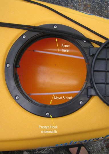
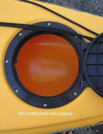
When the lines are installed, they will be exposed in the back hatch. However, on the inside edge of the hatch frame, there is a padeye which acts as a hook for the lines to remove them from sight.
There are some numbering errors in the instructions. For example, in my instructions in Step 25 it says "step 9 and 12." It should be "step 17 and 20."
It may be optimistic, but perhaps Hobie is working on the instructions as we speak, so some of these steps and errors may change and be corrected. Unfortunately, we have paid about $70 for an upgrade to correct a poor design, then we have to install it, and then Hobie sends out instructions with errors and omissions. I feel like I am a beta tester, but paying to do it. Hobie, it should not be that way.
Hopefully the new up/down lines are better thought out and executed than the instructions.