aschaffter wrote:
As the issue is becoming extremely clouded, with a number of partially incorrect assumptions and drawings, and who agrees/disagrees with what. I'll just add a few statements-
To Matt M, I never addressed mast rotation, tacking, etc. with an Aussie rig vs original jib halyard but I said, and stand by my original statement that the claim that the Aussie rig reduces mast compression (by 60%?) is totally, flat out, wrong. Nothing I have seen in this thread refutes that.
ALL lines attached to the mast originating or ending somewhere else (bridle, hulls, etc.), that are not perpendicular to the mast, and are tensioned (not slack) or have reactive forces on them (wind, wave action) have a vector component parallel to and through the the mast- these are compressive forces on the mast. Since they are external forces they must be balanced to zero with external forces (from lines or structure.) If not the mast will move up or down, i.e. if you a put force on any unrestrained object (no opposing force), the object will move- a ball, a car, the boat on the water, etc.
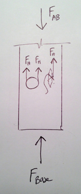
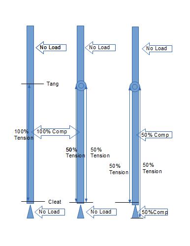
As to the block diagram- the diagram on the right is wrong. 50% + 50% = 100% (not 50%), vector forces are additive! You'll have 100% compressive force and 100% countering it at the step! Think about it, adding multiple sheaves doesn't change the original force it just reduces the effort by mechanical advantage. If that block is only rated at 50% you'll have a big surprise if you tension each line to 50% like you show!
The main halyard in fact does impart mast compression too, in two ways- internally from the cleat, through the masthead sheaves to the downhaul cleat (and it is not affected by the number of sheaves on the downhaul blocks). And to a lesser degree by external forces- the weight of the sail and boom, and by wind through the main sheet. This force is shared with the forestay/jib halyard (and upwind shroud). These external forces are countered by the boat through the step/foot.
We all agreed pages ago that the total compression load on the mast is not reduced by 66% buy the Aussie halyard system. You can drop that now.

The discussion is now about these points:
1. Can a compression load in line with the mast exist without changing the load measured at the step? The answer is Yes.
2. Does the placement of the cleat (point that pins the load) on the Jib Stay/Halyard system effect compression in the mast section?
3. Does the placement of the tension adjusting mechanism have an effect on either the compression load on the mast or the compression load on the step?
4. What effect results from these forces?
You are correct about my diagram, it is not a complete representation of the vectors, that is why it was not labeled that way. The force that turns the load 180 degrees remains 2x leg load so the there is still a 100% load at the turning point (and within the mast section). What I was trying to illustrate is that moving only one leg of the system off the mast transfers only that leg's load to the step. If we don't agree on that point we can stop and share a drink.
For clarity, lets look at a single point (the tang) fixed to an infinitely stiff beam. To that point are fixed (shackled) two infinitely stiff wires. The other ends of the wires are also fixed to the infinitely strong beam at a single point and each wire is placed under 100 units of tension with a 3:1 tackle.
The load in the beam is 2x the load on the wires.
Replace the shackles at the tang with a pulley. Does the load on the tang change?
The pulley allows the load on both sides of the system to be equal with only one adjustment tackle.
It does not matter were on the wire or on which side of the pulley the adjustment tackle is as far as static loads on an infinitely stiff system.
How then does the Aussie 3:1 differ from the standard 3:1?
It is obvious that once the tensions are set it does not matter where the adjustment is *if nothing moves*.

R